

KYN61A-40.5 Metal-clad AC Draw-out Switchgear
KYN61A-40.5 Metal-clad AC drawout switchgear is designed by Xi'an High Voltage Apparatus Research Institute and developed by Shanghai Delixi Group Co. Ltd.
KYN61 A-40.5 Switchgear is equipped with ZN85A, ZN85B vacuum circuit break, or SF1, SF2 from Schneider Company, or FP series SF6 circuit breaker from ALSTOM Company. The switchgear adopts assembled structure, which improves the appearance and production precision. The busbar adopts pyrocondensation insulating material and epoxy coating insulation. The shape of the electrode is optimized with a compact cabinet structure. It has perfect"5-defend"functions. KYN61 A-40.5 Switchgears are used for 40.5kV three phase AC 50Hz electric power system. They are used to distribute electric power for power plants, electrical substation and power distribution control rooms of industrial and mining establishments. It can control, protect and monitor electric circuits. Except for general electric power system, they can also be used in places where a lot of operations are in need. The working environment is in accordance with normal working environment prescribed in GB3906"3.6-40.5kV AC Metal Enclosed Switchgear".
Model Specification 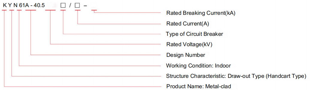
Technical Parameters
1. Rated Parameters of KYN61A-40.5 Switchgear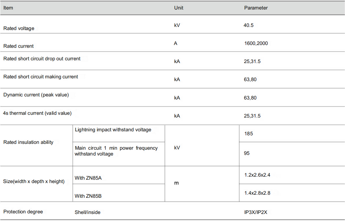
2. Rated Parameters of KYN61A-40.5 Switchgear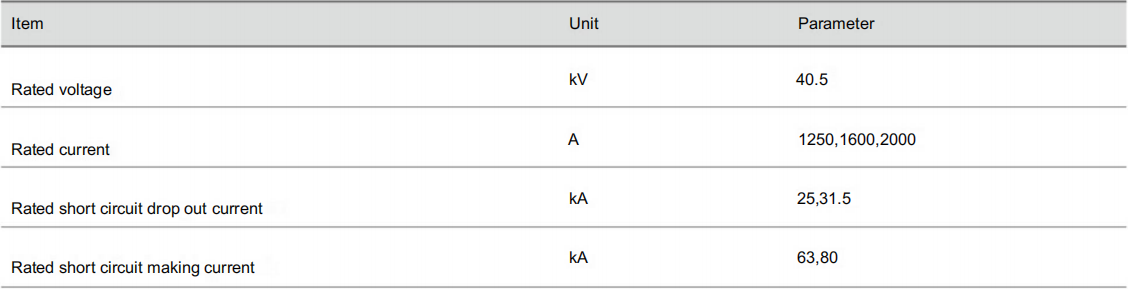
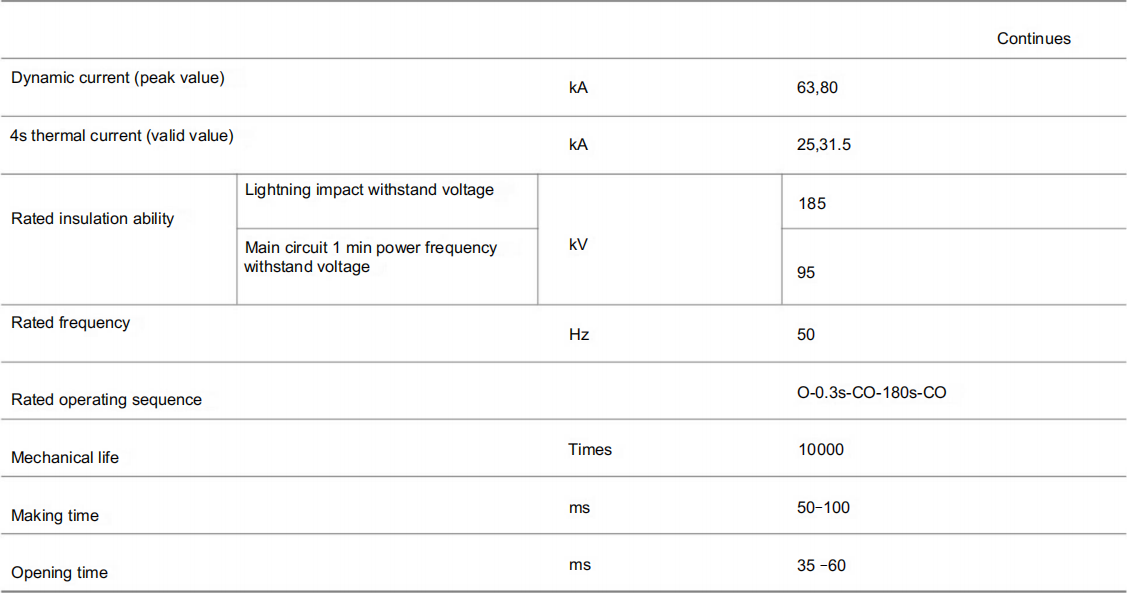
3. Rated Parameters of ZN85B-40.5 Vacuum Circuit Breaker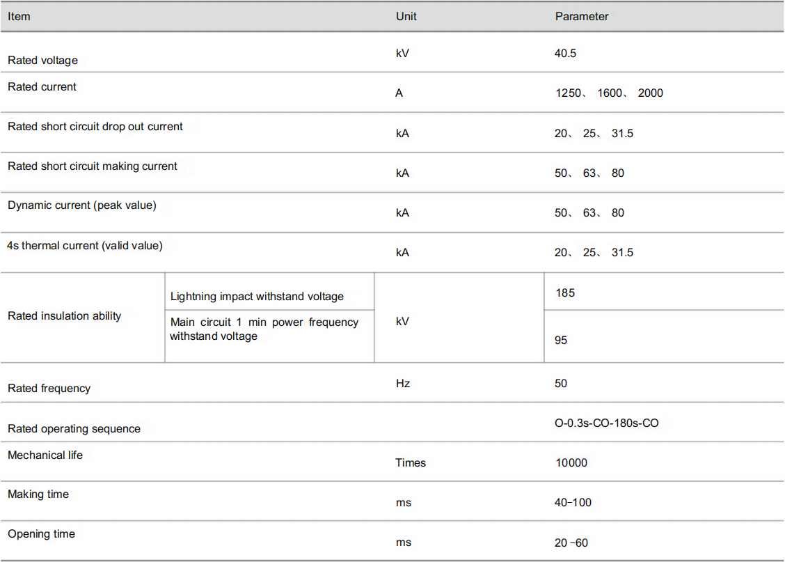
4. Rated Parameters of FP 40 series SF6 circuit breaker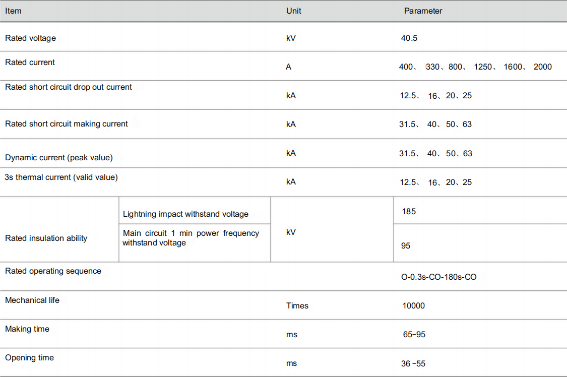
5. Rated Parameters of SF Series Schneider SF6 circuit breaker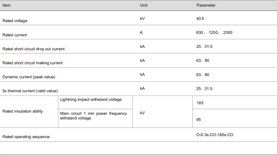
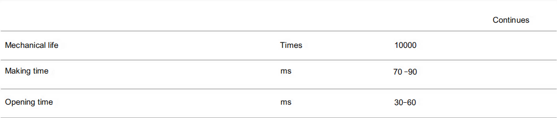
6. Rated Parameters of ZN85B-40.5 Vacuum Circuit Breaker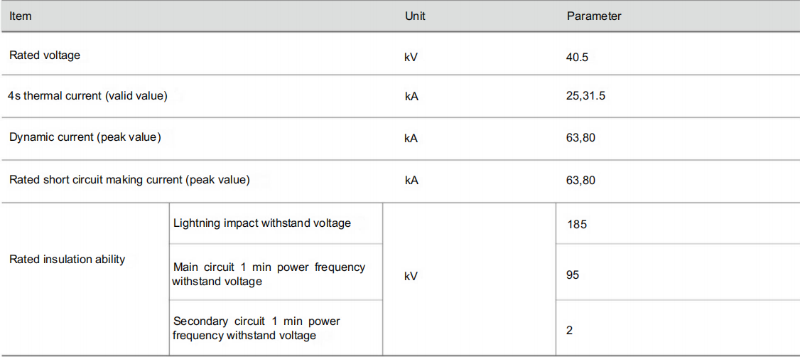
Structure Characteristics
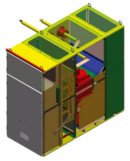
The draw out switchgear consists of two parts, one is cabinet and the other one is handcart. The main cabinet is made of bending sheet steel and assembled by bolts. The classic scheme (see Figure 2), the cabinet has four sections, such as relay meter cabinet, handcart room, cable room and bus bar in terms of the electric equipment functions inside the switchgear. Each part is separated by the earthing metal separator. Protection level of its shell is IP3X. When the door of handcart opens, the circuit breaker handcart is at breaking/test position with a protection level of IP2X. The switchgear has several kinds of schemes, including incoming and outgoing cables, incoming and outgoing overhead cables, busbar connections, disconnector, voltage transformer, lightning arrester. In the cable room, there are current transformers, earthing switch. More cables can be connected owning to enough spare space. A metal valve is installed in front of the contact box. The upper and lower valves open automatically when the handcart moves from breaking/test position to the operation position. On the contrary, they close when the handcart moves backwards to form separation zone.
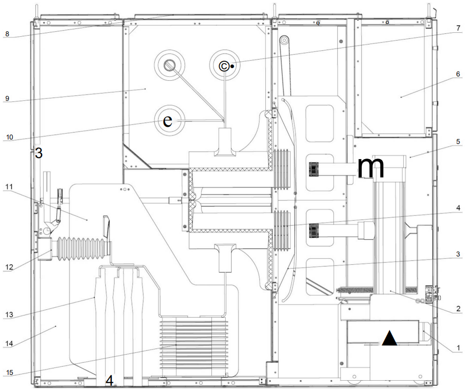
1. Secondary plug 2. Circuit breaker handcart 3. Valve
4. Contact box 5. Circuit breaker room 6. Meter room
7. Busbar casing 8. Pressure relief covers 9. Busbar room
10. Main busbar 11. Insulation separator 12. Earthing switch
13. Power cable 14. Cable room 15. Current transformer
1. Circuit Breaker Handcart
A fully insulated vacuum circuit breaker or SF6 circuit breaker is installed in the handcart. Handcart frame is equipped with screw nut feed mechanism and overrunning clutch. The screw nut feed mechanism can be operated easily to make handcart move between breaking/test site and operation site. With the help of screw nut self-locking performance, handcart can be locked at operation site stably, defending the force occurred by electrodynamics. The overrunning clutch will work after handcart moves to breaking/test site and before handcart moves to operation site. It makes operation shaft blank spin by separating it from guide
screw axis. This design avoids fault operation to damage the feed mechanism.
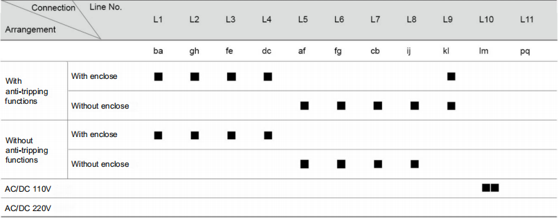
Interlock devices between main switch, handcart, earthing switch and cabinet doors, which are applied mandatory mechanical latch. It satisfies “five-defend” function. The circuit breaker can be closed only when the circuit breaker handcart is on the breaking/test site or working site. In addition, when the circuit breaker is closed, the handcart feed mechanism cannot work, in order to avoid moving circuit breaker handcart with load. The circuit breaker handcart can move from breaking/test site to working site only when the earthing switch is separated. The earthing switch can process switch-on operation only when the circuit breaker handcart is at breaking/test site. In this way, closing earthing switch with load is avoided. When the circuit breaker handcart is at test or operation site without control voltage, manual breaking can be processed while manual closing is not permitted. When the circuit breaker handcart is at the operation site, the secondary plug is locked and cannot be removed.
The main busbar is supported by the branch busbar and busbar bushing. Adjacent cabinets are separated with busbar bushing .It stops accidents spreading effectively, as well as be as support for the busbar. The busbar adopts shrinking insulating bushing or vulcanization coating technology to form a reliable compound insulation.
Voltage monitoring insulator is combined with the earthing switch as a whole. The terminal display device is placed at the front of the switchgear. It can emit visible light at 50% of the rated voltage. As a result, it provides a reliable human safety solution.
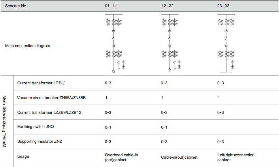
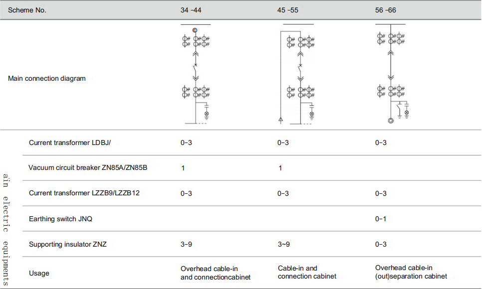
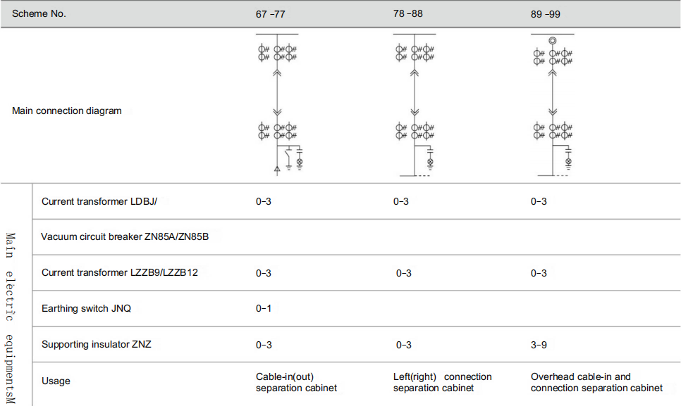
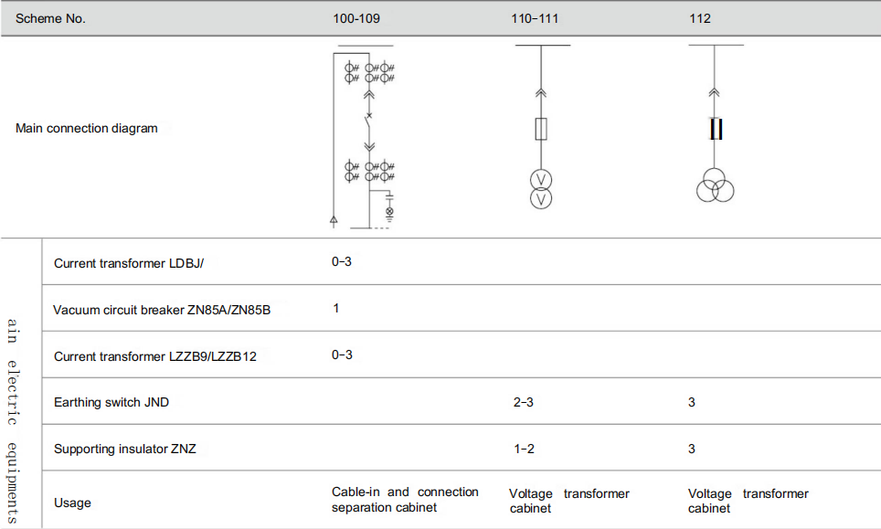
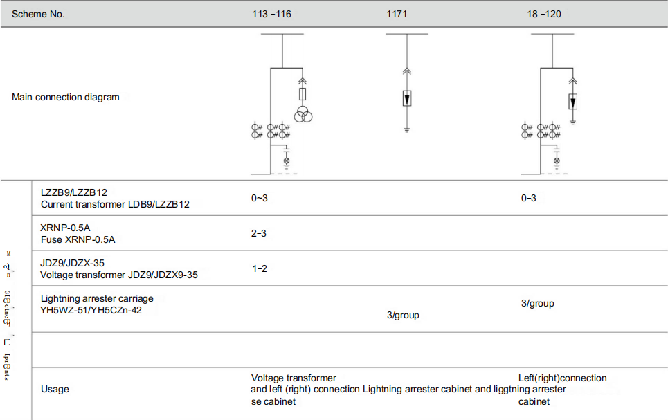
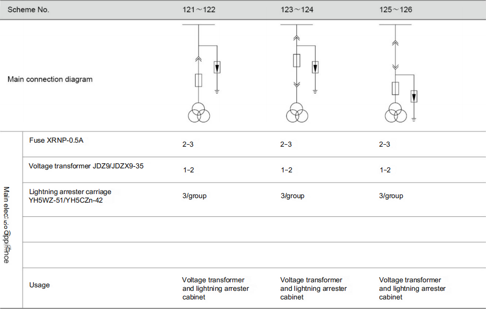
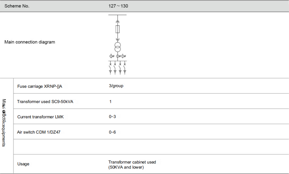
Primary connection schemes
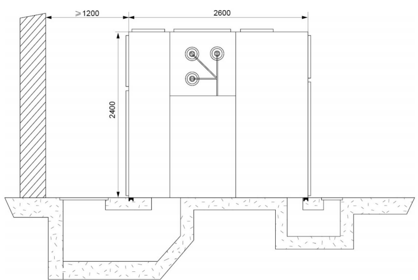
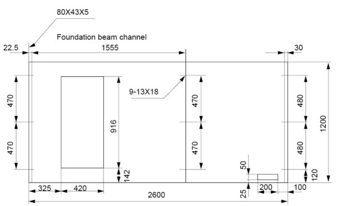
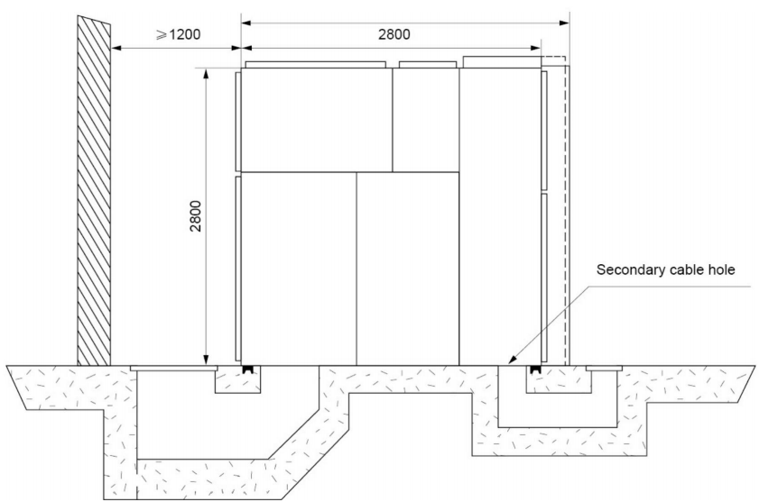
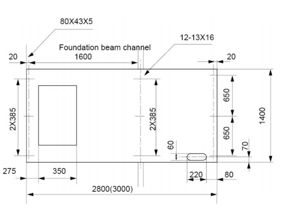
Scheme of foundation installation